
PCB functional testing, test fixtures and test procedures
PCB functional testing answers one question for every unit: does it do what it was designed to do, every time. We write the test procedure from your requirements, build the fixtures and scripts to run it, and test prototypes, pilot batches and production units, so faults are found on our bench and not at your customer's site.
Beyond power and continuity
A board can be perfectly soldered and still be wrong. An inverted LED signal confuses the user; a misconfigured serial port loses the connection to the cloud; a timing error stops a safety relay from opening. Electrical checks will not find these. A functional test exercises the device the way it will be used:
Inputs and outputs, from buttons and switches to relays and actuators
Sensor readings against known reference values
Communication over UART, RS-485, I2C, SPI, CAN, Ethernet, Wi-Fi or cellular links
Displays, LEDs and the user interface
Timing, watchdogs and recovery after a fault
How we test
Test procedure from the design
Testing starts from your functional requirements, the schematic and the firmware's expected behavior. We add the corner cases: power applied slowly, inputs changing at the wrong moment, a lost connection, a supply below its rated voltage. The result is a written test procedure with a pass or fail limit for every step.
Bench testing for prototypes
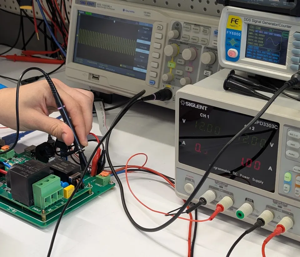
The first units are tested on the bench, with oscilloscopes, logic analyzers, bench power supplies, electronic loads and protocol analyzers for UART, Modbus and CAN. This is where the design is validated, and where the test procedure itself is proven before it is used on a batch.
Test jig development for batches
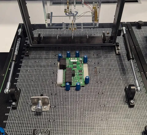
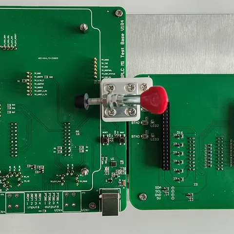
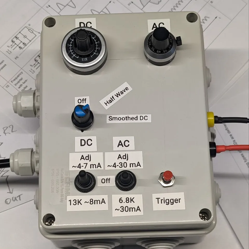
Testing a batch by hand is slow and depends on who does it. For pilot runs and production we build a functional test fixture for the board: pogo pins or connectors to reach the test points, a clamp to hold the board, and the supplies, loads and simulated signals it needs. A script runs the steps, compares each reading with its limit and records the result against the serial number. We also build dedicated test equipment where none exists, such as a box that sets adjustable AC and DC test currents.
End-of-line testing at the factory
When production moves to a partner factory, the same fixture and script can travel with it for end-of-line testing, so every unit is tested the same way wherever it is built. We supply the fixture with its instructions and review the first results.
Examples of what we test
Inputs and outputs
Switches, relays and GPIO states change as commanded.
Interfaces
Command and response over UART, RS-485, I2C, SPI and CAN, with signal quality.
Displays
Screens, encoders and buttons follow the interface logic.
Sensors
Temperature, current and voltage readings within tolerance.
Power
Start-up sequence, reset, and behavior at under- and over-voltage.
Connectivity
Wi-Fi, Ethernet or cellular connection, loss and reconnection.
Memory
Settings and logs kept through power cycles.
What you receive
A written test procedure with limits for every step
Test results per unit, by serial number
For batches: the test fixture, its scripts and operating instructions
A fault report for any unit that fails, with the cause and the fix
Where testing fits
Functional testing follows SMT assembly, through-hole assembly or box build assembly, and comes before compliance testing. Test points are best planned during PCB design, which is why we add them from the first layout. We test devices for EV charging, industrial control and motor control.